After ordering a CD-Pro2M unit and searching the Internet for inspiration and info, I started making a wish list for the controller.
- PIC microprocessor
- DSA control lines to communicate with the CD-Pro unit
- Keyboard matrix 3×3
- RC5 remote control
- LCD or LED display 2×16 characters
- Eight relay outputs
- Two Sensor inputs (cover open/close)
- ICSP In Circuit Serial Programming
- SMPS (Switch Mode Power Supply) for low power consumption
- EMC mains filter
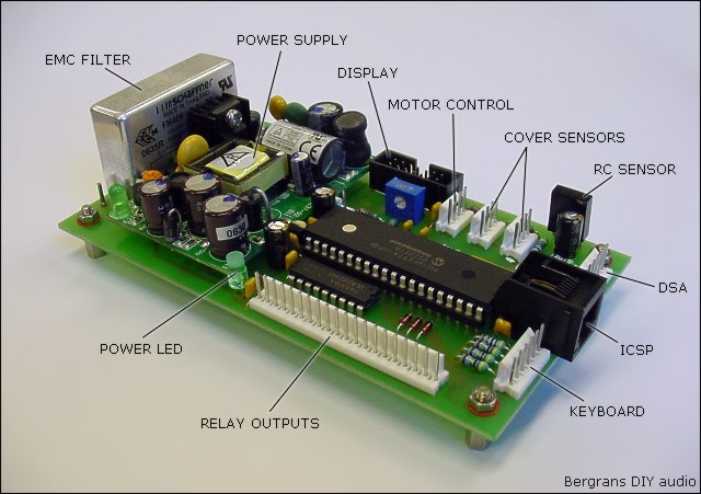
That’s quite some I/O so I picked the PIC16F871, a 40 pin microcontroller, to do the trick. Adding a 10MHz crystal, a remote control sensor and a relay driver (ULN2803) and we are off. Here you find the first proto-type pcb. For the actual version changes are made to the ICSP and sensor connectors. These are the resulting schematics. The resulting PCB is 136x73mm including SMPS and line EMC filter. And here you find the component placement of the pcb. The PCB is a single sided design to make life easy. A couple of wire bridges (5) on the component side will do the rest.
I use the low cost all-in-one debugger/programmer MPLAB ICD2© from Microchip, but any ICSP for PIC controllers will work.
Circuit description
All hardware is controlled by the PIC (16F871) microcontroller. The controller uses a 10Mhz crystal (X1) for clock generation, connected to the pins 13 and 14. The diode D2 in the default reset circuit on MCLR (pin 1) enables the microcontroller to be programmed in circuit (ICSP).
DSA-interface
On port A of the PIC16F871 we find the DSA interface lines for the CD-Pro2M unit. DSA (Data Strobe Acknowledge) is the protocol used by all CD-Pro units. RA0 is the ACKNOWLEDGE, RA1 the DATA and RA2 the STROBE line of the DSA interface. RA3 can reset the CD-Pro unit, diode D4 allows the CD-Pro unit to pull the reset line high on power up, to reset, even if RA3 is set low. RA4 controls the LASER OFF pin, pulling this line low will switch off the laser (used for safety). All lines are pulled up by the resistor array R5. For protection series resistors (R6, R8, R9 and R10) are added to the DSA lines. J3 has the same pin layout as the DSA interface connector on the CD-Pro unit.
Remote control
For remote control I use the TSOP1236 receiver. The decoded RC5 signal goes to port RB0. This port can be set as an edge triggered interrupt port. So you don’t have to scan this port in a software routine. The supply voltage for the RC5 receiver is filtered by R14/C14 as stated in the datasheet.
Keyboard
Port B (RB1…RB6) is used for the keyboard. A 3×3 switch matrix can be connected to J4. This means 9 buttons can be used. I will use one to detect the state of the power switch. The rest to control the CD functions (Start, Stop, Pause, Next, Previous, Search forward, Search backward and Repeat). Port RB6 is also used for ICSP (programming/debugging).
Display
To save some I/O pins the LCD display (2 lines of 16 characters) is controlled in 4 bit mode. The lower “nibble” bits (4 bits) of port D are used as data bits. The control bits (RS register select, RW read/write and E enable) are on port C. The display brightness can be controlled in some different ways. First by trimming R4 to the right value. If port RC2 is set as input this port has no effect on the brightness. When RC2 is set as output and pulled high or low the brightness of the display will change. An other way of setting the brightness completely by software is using RC2 as PWM output, R7/C6 will act as a low pass filter (R4 should not be installed). By setting the PWM register value you can change the brightness (DC) voltage BTV. Some LCD displays don’t like BTV voltages below 2,5V so a 2,4V zener diode (D3) can be installed to prevent this. 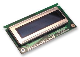 The display unit I’m using is a PLED 2×16 display. Giving high contrast green characters on a black background. It’s controlled and connected like a normal (2×16) LCD display unit.
Remark: After using the PLED display for about half a year, character pixels that are on most of the time start to fade. I was already warned about the short live cycle of the PLED display, and now it’s seems to be true. A common LCD display might be a better choice after all.
Relay outputs
This controller not only controls the CD-Pro unit but the whole CD player. So for switching on and off the power of different power supplies I use (12V DC) relays. To control these relays there is an eight channel relays driver on the PCB (U4). Each output can sink 500mA and is protected by clamp diodes. The 10W on-board power supply can only supply 800mA so be careful with the total load connected. The last channel (U4 pin 11) of the relay driver is used for the power indication LED (D8) and powering the sensors (J8 and J9). This to reduce power consumption in standby mode.
Sensors
The sensor connectors (J8 and J9) are general purpose I/O connections. They will be used to detect if the cover is open or closed. I use a slotted opto-coupler connected to J8 as drawn here. In this case LED current is set by R16 ( If = (12-Uf)/R16 ). You could also use a micro switch on the pins 1 and 2. The sensor inputs are pulled up to VDD (+5V) by resistors R15 and R18.
Be aware these inputs are active “low”. This means pin 1 of J9 should be pulled to ground when the cover is closed. When using switches instead of slotted opto-couplers use switch contacts that close when activated (Normally Open) connected between pin 1 and 2 of J8/J9.
Motor control
The actual motor driver, to open/close the cover, is not on this PCB. The signals CW/CCW and ENABLE on J10 are to control a motor driver. Do not use the +12V and GND on J10 to power the motor!
Power supply
To power the controller a SMPS (Switch Mode Power Supply) is used. This 12V/10W power supply is an open frame PCB mount power supply with efficiency up to 75%. A LM78L05 is used to regulate 12V to 5V (VDD) to supply the PIC controller and the LCD display. This VDD supply is limited to 100mA, so when using a LCD display with backlighting use the 12V for the backlight LED’s where possible. Capacitors C7…C12 are for decoupling near the semiconductor parts.
Bill Of Material
 Most components are easy to find. Farnell/InOne supplied the power supply (100-5642) and EMC filter (119-1336). The power supply can be replaced by a 12V linear or SMPS off board power supply. If you can’t find the resistor arrays make them yourself as shown here. The IR remote control receiver TSOP1236 can be replaced by other 36kHz or 38kHz IR receivers.
| Controller Bill Of Material (BOM) | ||
|---|---|---|
| Resistors | ||
| R1 | 470R | |
| R2 | 10k | |
| R3, R16, R17, R20 | 1k | |
| R6, R8, R9, R10, R11, R12, R13, R14 | 47R | |
| R7 | 6,8k | |
| R5 | 4606X-101 47k | 5 resistor network Bourns |
| R15, R18 | 47k | |
| R4 | 10k | trimmer |
| Capacitors | ||
| C1, C4, C14 | 33uF/25V | radial electrolytic |
| C2 | 100nF | MKT 0,2″ pitch |
| C3, C5, C7, C8, C9, C10, C11, C12 | 22nF | X7R ceramic 0,2″ pitch |
| C6 | 470nF | MKT 0,2″ pitch |
| C15, C16 | 33pF | ceramic 0,1″ pitch |
| Semiconductors | ||
| D1, D4, D5, D6, D7 | 1N4148 | |
| D3 | Zener 2,4V | 500mW |
| D8 | LED | power indicator |
| U1 | 78L05 | voltage regulator |
| U2 | PIC16F871 | microcontroller |
| U3 | TSOP1236 | IR receiver |
| U4 | ULN2803 | relay driver |
| Misc | ||
| X1 | 10MHz Xtal | |
| LF1 | FN 406-0.5 | EMC line filter |
| PS1 | ACS10US12 | SMPS 12V/10W |